

O que é kerf? Por que suas junções cortadas a laser não encaixam
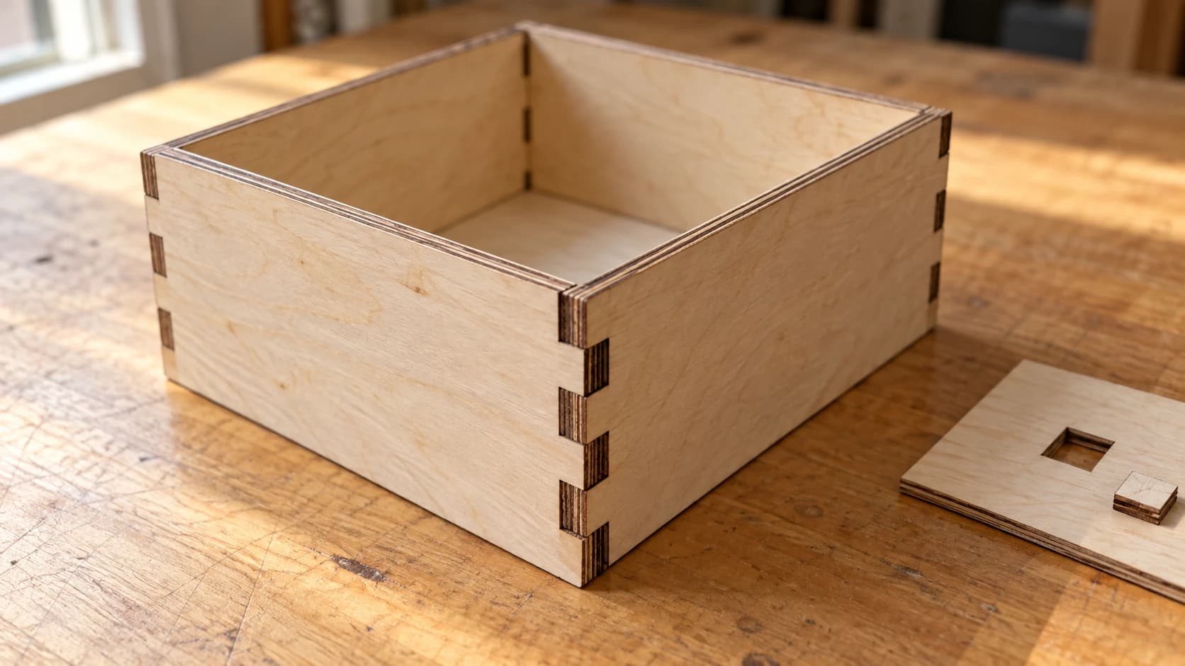
Você mediu tudo. O gerador de caixas pediu compensado de 3 mm, você colocou compensado de 3 mm, e as junções de dedos ainda ficam chacoalhando nas ranhuras como dentes soltos. Ou você cortou um furo para uma cavilha de 6 mm e ela caiu direto, sem encostar nas laterais.
Não há nada de errado com o seu arquivo. Você acabou de conhecer o kerf.
Dica
Resposta curta: kerf é a largura do material que sua máquina remove ao longo da linha de corte. O feixe ou a fresa têm uma largura real, então cada corte remove um canal estreito, e não uma linha perfeita de largura zero. Por isso, as peças ficam um pouco menores do que o desenho, os furos ficam um pouco maiores e as junções ficam frouxas.
A palavra é mais antiga do que qualquer uma das nossas máquinas. Kerf originalmente significava a ranhura deixada pela lâmina de uma serra em uma tábua, e os carpinteiros calculam isso há séculos. Seu laser herdou o problema, apenas em uma escala muito menor.
O problema da linha do marcador
Aqui está todo o conceito em uma única imagem que você pode guardar na cabeça.
Seu software de design desenha com um lápis infinitamente afiado. Uma linha em um SVG tem posição, mas não tem largura. Sua máquina, porém, corta com um marcador. O feixe ou a fresa remove um canal de largura real, centralizado na linha do seu lápis.
Essa parte central é importante. Metade do canal fica de um lado da sua linha, e metade do outro. Assim, cada borda cortada da sua peça final fica a cerca de metade de um kerf de distância de onde você desenhou, nos dois lados, em cada corte, em todos os pontos do design.
Desenhe um quadrado de 20 mm e corte ao redor dele. O canal consome metade de um kerf para dentro em todo o contorno, então o quadrado que você pega da mesa fica um kerf inteiro mais estreito do que 20 mm. Enquanto isso, o furo quadrado deixado na chapa fica um kerf inteiro mais largo do que 20 mm. A mesma linha, dois resultados diferentes, dependendo de qual lado do corte você mantém.
Esse é todo o mistério. Todo o resto deste post consiste apenas em medir o canal e decidir o que fazer com ele.
IMPRIMA. CORTE. ENTALHE.
- Vários formatos (SVG, DXF, PNG)
- Designs testados em máquinas
- Licenças comerciais
Patrocinado por PrintCutCarve.com
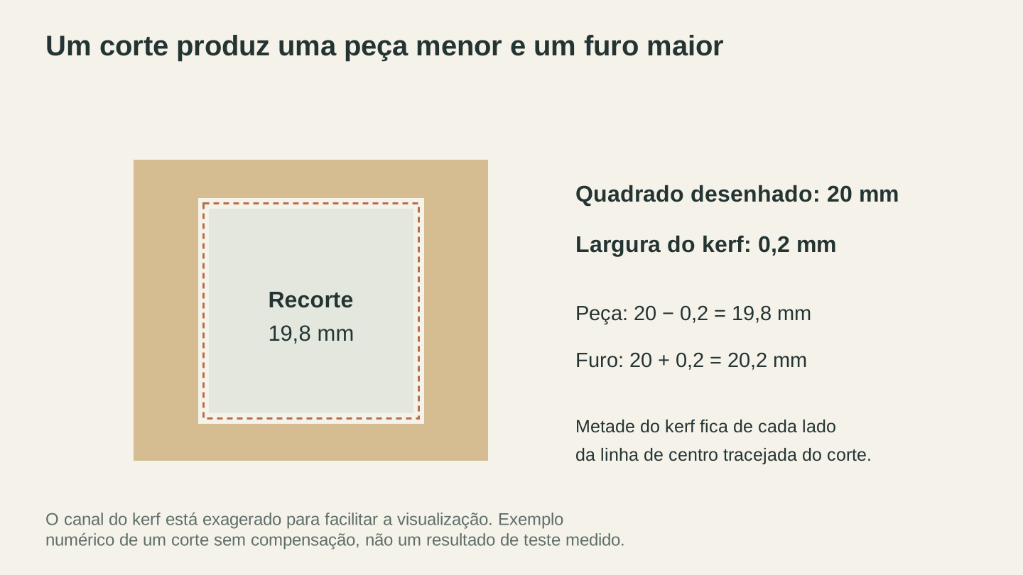
Com um kerf de 0.2 mm centralizado em um percurso quadrado de 20 mm, a peça mede 19.8 mm de largura e a abertura mede 20.2 mm. O diagrama amplia o kerf para facilitar a visualização.
Qual é o tamanho do kerf em cada máquina?
Kerf não é um único número. Ele depende da máquina e, dentro de uma mesma máquina, varia conforme o material, a espessura, o foco, a potência e a velocidade. Mas vale conhecer a ordem de grandeza por processo, porque isso indica quando você precisa se preocupar.
| Processo | Comportamento típico do kerf | O que o cria |
|---|---|---|
| Laser de CO2 ou diodo | Fino, normalmente em torno de 0.1 a 0.3 mm | O feixe focado queima ou derrete um canal estreito |
| Fresadora CNC | O diâmetro total da fresa, geralmente 3.175 mm (1/8 inch) ou mais | A fresa giratória remove fisicamente a própria largura |
| Faca de arraste (cortadora de vinil) | Efetivamente zero em vinil fino | A lâmina separa o material em vez de remover um canal |
| Serra de bancada | Normalmente alguns milímetros, dependendo da lâmina | A largura da lâmina e o travamento dos dentes, o significado original de kerf |
Duas coisas se destacam nessa tabela.
Primeiro, o kerf da CNC é enorme em comparação com o do laser, mas os fluxos de trabalho CNC lidam com isso há tanto tempo que a solução já vem integrada. Seu software CAM pergunta se deve cortar por dentro, por fora ou sobre a linha. Essa pergunta é a compensação de kerf usando outro nome, e respondê-la corretamente faz a largura da fresa praticamente desaparecer das dimensões finais. Já o software de laser normalmente corta sobre a linha por padrão e deixa o problema discretamente com você. Se estiver comparando as duas máquinas, nossa comparação entre cortadora a laser e fresadora CNC explica melhor diferenças como essa.
Segundo, uma cortadora de vinil tem praticamente nenhum kerf relevante em materiais finos. A lâmina separa o vinil como um zíper, em vez de vaporizar um canal (o software ainda tem uma configuração de deslocamento da lâmina, mas ela corrige o movimento da lâmina ao girar, não o material removido). Se você veio do mundo das máquinas de corte, é por isso que as junções a laser foram uma surpresa.
Por que as peças ficam pequenas e os furos ficam grandes
Depois que você entende que o canal é centralizado na linha, os sintomas clássicos se explicam:
- Os perfis externos ficam menores. A borda se move para dentro pela metade de um kerf em cada lado, então qualquer dimensão externa diminui em um kerf inteiro.
- Os furos e recortes ficam maiores. A borda se move para fora pela metade de um kerf em todo o contorno, então o furo aumenta em um kerf inteiro.
- As junções sofrem duas vezes. Uma junção de dedos é um dedo estreito entrando em uma ranhura. O dedo perde um kerf, a ranhura ganha um kerf, então a folga total entre eles é de aproximadamente dois kerfs. Em um laser, isso pode representar 0.3 a 0.4 mm de folga, exatamente o suficiente para fazer uma junção de caixa chacoalhar em vez de se encaixar sob pressão.
É por isso também que a compensação segue nessa direção. Para chegar às dimensões pretendidas, o furo desenhado precisa ficar menor e a peça desenhada precisa ficar maior, cada um em um kerf, para que o material consumido pela máquina os traga de volta ao tamanho correto.
Antes de alterar qualquer coisa, porém, você precisa do seu número real.
Como medir seu kerf
Não use um valor de kerf de uma publicação em um fórum ou da máquina de um amigo. O kerf muda conforme a lente, a altura do foco, o material, a espessura e as configurações de potência e velocidade. O único número que realmente importa é o que você mediu na sua máquina, no material do projeto e com as configurações do projeto.
O teste leva alguns minutos e requer um paquímetro. Paquímetros digitais baratos servem.
- Desenhe um quadrado simples de tamanho conhecido, por exemplo, 20 mm, no software de design.
- Corte-o na mesma chapa que você usará no projeto real, com as configurações exatas que usará nos cortes reais.
- Meça o quadrado cortado nos dois eixos. A leitura ficará abaixo de 20 mm.
- Meça o furo que ele deixou na chapa. A leitura ficará acima de 20 mm.
- Seu kerf é a diferença da peça (tamanho desenhado menos peça medida), e você pode conferi-lo comparando com o excesso do furo (furo medido menos tamanho desenhado). Os dois valores devem ser aproximadamente iguais.
Por exemplo, se o quadrado desenhado de 20 mm medir 19.8 mm, seu kerf será 0.2 mm, o que significa 0.1 mm por lado. Esse valor por lado, metade do kerf, é o que a maioria das ferramentas de deslocamento espera.
Dica
Quer mais precisão? Corte dez tiras separadas de 10 mm sem aplicar compensação, junte-as e meça a fileira em relação aos 100 mm que ela deveria ter. Cada tira fica menor por um kerf, então a diferença dividida por dez é o seu kerf, com a oscilação do paquímetro diluída pela média.
Anote o resultado. O kerf por material e espessura é um daqueles números que vale a pena manter em um post-it perto da máquina, porque quase não muda até que você troque a lente, o material ou as configurações.
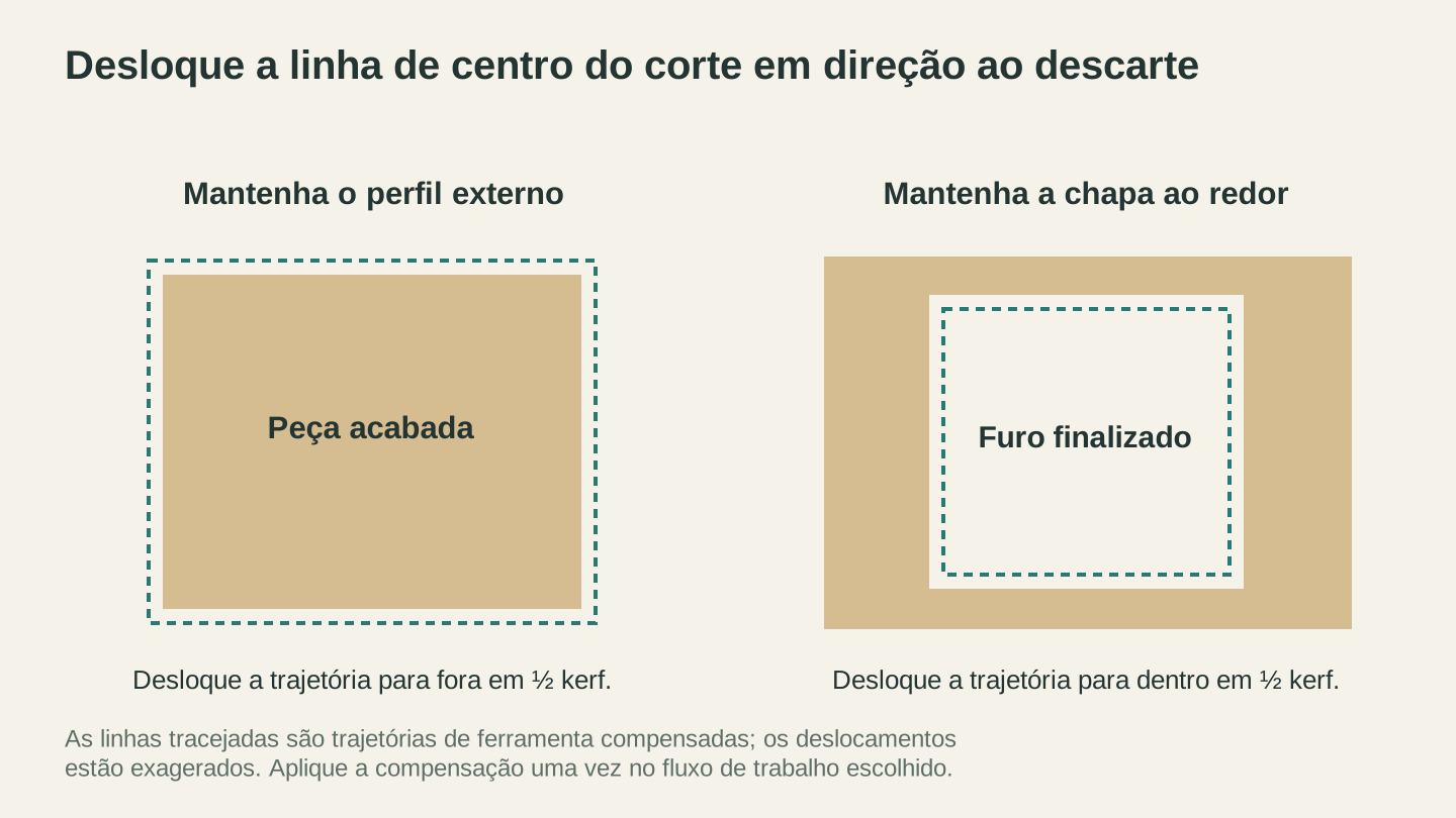
Desloque a linha central do corte em direção ao lado do descarte pela metade do kerf medido. Aplique essa compensação uma vez no fluxo de trabalho escolhido de design ou software da máquina.
Compensação de kerf: quatro maneiras de corrigir o encaixe
Você tem um número. Agora aplique-o uma única vez, em exatamente um lugar.
- Deixe o gerador fazer isso. Os geradores de caixas e junções quase sempre têm um campo de kerf. Insira o kerf medido, e o gerador ajustará cada dedo e ranhura para você. Para marcenaria, esse é de longe o caminho mais fácil.
- Desloque os caminhos no software de design. A maioria dos editores vetoriais tem uma função de deslocamento ou expansão. Aumente os perfis externos pela metade de um kerf e diminua os furos pela metade de um kerf. É trabalhoso em designs complexos, mas funciona em qualquer lugar.
- Use a configuração de deslocamento de kerf do software do laser. Muitos programas de corte podem aplicar o deslocamento no momento do envio, mantendo seu arquivo de design limpo e nas dimensões reais.
- Na CNC, responda honestamente à pergunta sobre o percurso da ferramenta. Por dentro para furos, por fora para perfis, e o software CAM cuida do diâmetro da fresa. Cortar sobre a linha só faz sentido quando a geometria já foi compensada em outro lugar.
Aviso
Aplique a compensação em um único lugar. Se o gerador de caixas adicionar kerf e o software do laser adicionar novamente, as junções ficarão apertadas demais por dois kerfs, e você terá de lixar os dedos em vez de colar folgas. Apertado demais dá para corrigir, mas é irritante. A compensação duplicada é a maneira mais comum de as pessoas exagerarem na correção.
Depois que o design for compensado, aplica-se a logística habitual dos arquivos. Se o software da sua máquina exigir DXF em vez de SVG, o File Converter faz a conversão sem cobrança de créditos de ferramenta, sem créditos, e mantém sua geometria intacta. Se você não tiver certeza de qual formato deve ser a base do seu fluxo de trabalho, nossa explicação sobre DXF e SVG resolve a questão. O download do arquivo convertido exige um plano pago ativo.
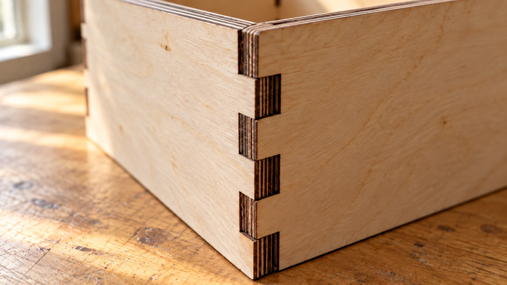
Uma vista mais próxima da mesma caixa mostra onde as dimensões da lingueta e do encaixe se encontram. O ajuste depende do material e do corte reais, então use uma pequena amostra da junta antes de cortar cada painel.
Quando o kerf importa e quando ignorá-lo
Esta é a parte que evita que você pense demais: a maioria dos cortes não precisa de compensação de kerf.
Faça a compensação quando as peças precisarem se encaixar:
- Junções de dedos e junções de caixa
- Encaixes de lingueta e ranhura
- Peças de encaixe sob pressão, furos para cavilhas, assentos de rolamentos
- Inlays, nos quais a peça e o rebaixo se movem em direções opostas e os erros se acumulam
- Engrenagens, dobradiças e qualquer peça mecânica
Ignore-o quando nada tocar a borda:
- Gravação, que nunca atravessa o material e não tem nenhuma borda de encaixe
- Silhuetas decorativas, ornamentos e arte de parede
- Porta-copos, toppers para bolo e placas
- Estênceis, a menos que o estêncil seja destinado a algo dimensionalmente crítico
A regra prática é: se a peça nunca precisar se encaixar em outra, um décimo de milímetro não muda nada que alguém perceberá, e seu tempo será melhor empregado em outra coisa. Trace uma foto ou um logotipo em um SVG limpo com o MonoTrace, grátis e sem créditos, corte-o como arte de parede, e o kerf nunca entrará na conversa. Ele só se torna real no dia em que duas peças precisam se segurar.
De qualquer forma, o kerf é apenas um item da lista de verificação antes do corte. Nosso guia sobre preparar arquivos para corte a laser aborda o restante do que você deve conferir antes de pressionar iniciar.
Perguntas frequentes
O kerf é igual para todos os materiais no mesmo laser?
Não. Materiais diferentes queimam de maneiras diferentes nas mesmas configurações, e a espessura também importa. Meça por material e espessura e reutilize o número até que algo na configuração mude.
Por que as bordas cortadas a laser ficam ligeiramente inclinadas?
O feixe é focalizado em uma cintura estreita e se espalha acima e abaixo dela, então as paredes do corte podem sair ligeiramente cônicas, em vez de perfeitamente verticais. Quanto isso acontece e em qual direção depende da altura do foco e da espessura do material. Em materiais finos, quase não é perceptível. Em materiais espessos, pode afetar o encaixe das junções, o que é mais um motivo para fazer um teste de encaixe no material real.
Posso simplesmente usar o valor de kerf que alguém publicou para o modelo da minha máquina?
Use-o como uma estimativa inicial, não como resposta final. O estado da lente, o foco, o lote do material e as configurações alteram o valor real. O teste rápido do quadrado mostra a verdade sobre a sua máquina hoje.
Meça uma vez, encaixe para sempre
Kerf não é um defeito, e sua máquina não está quebrada. É apenas a largura do corte, e todo processo de corte já inventado tem uma. Os makers cujas caixas se encaixam não estão usando lasers melhores. Eles mediram um quadrado uma vez, anotaram um número e o inseriram no campo de kerf.
Então, na próxima vez que os dedos chacoalharem: corte o quadrado de teste, faça a subtração e corte novamente. E quando seu arquivo compensado precisar virar um DXF para a máquina, o File Converter cuida disso sem cobrança de créditos de ferramenta. Para tudo que for decorativo nesse meio-tempo, o MonoTrace transforma imagens em SVGs prontos para corte, também sem cobrança de créditos de ferramenta e sem precisar fazer contas de kerf. O download do arquivo convertido exige um plano pago ativo.
Ferramentas relacionadas
Pronto para experimentar estas ferramentas?
Cadastre-se grátis, sem precisar de cartão de crédito. Ferramentas gratuitas disponíveis imediatamente.
Começar grátis